CALL: +1-518-956-2980

Buy Now

Buy Now

Buy Now

Need parts?

Buy Now

Improved Accuracy and Resolution Using Point Source Emitter Technology

Point Source Emitter Definition

LEDs (Light Emitting Diodes), semiconductor light sources, have been introduced and developed for several decades. LEDs are applied in many devices as indicators and general illumination products such as lighting components. As a “green” light source, LEDs can provide long life time and high efficiency light for many applications. However, for some special applications, standard LEDs are not always the perfect choice. Point Source Emitters (PSEs) offer a great alternative in applications needing a precise beam of light such as encoders, machine vision and medical fiber.

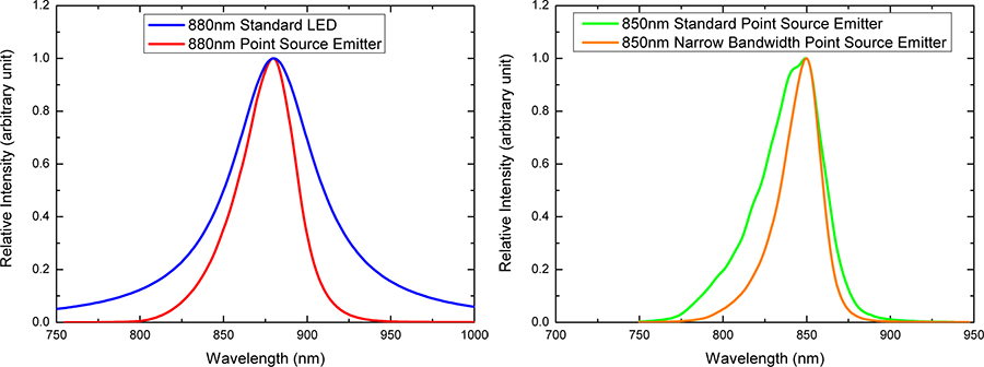
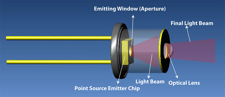
Point Source Emitter is a semiconductor diode similar in structure to a standard LED, however, the light is emitted through a well defined circular area, typically 25μm-150μm in diameter. The light produced appears as a “spot”. The output light produces very narrow, almost parallel viewing angles. These two characteristics are well suited for applications which require a near parallel light source and lower power, as compared with laser diodes.

Figure 1 shows side view structure of standard LED and PSE. First, the difference in these two structures is emitting light direction. Standard LED output light is directed to the side. In order to refocus the light direction, standard LEDs normally need a reflective cavity to force the light from side to top. This can cause light output loss, power dissipation, and variations in final output light beam and viewing angle. However, PSEs emit light to the upper surface though an aperture / window on top of the structure. Second, the difference in these two structures is the position of the cathode contact. The cathode contact pad of a standard LED is typically located in the center of the structure, which can obstruct light output due to the top wire bond. Point source emitters can easily solve this problem by locating the cathode contact wire bond to the side of the aperture window, eliminating any obstructions and dark spots (represented in figure 2). The light emitted from the standard LED (left in figure 2) has several dark spots due to the bonding pad, obstruction from the wire bond as well as the reflector cup (shown in figure 3). Point source emitter (right in figure 2) has a much more narrow, defined, and precise beam with no dark spots.

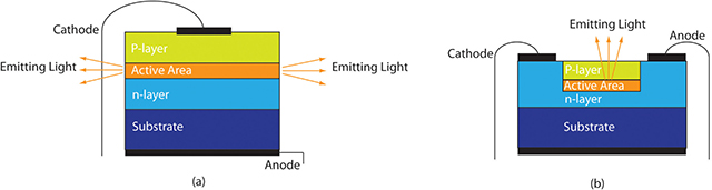
Figure 1, Side View Structure of Standard LED and Point Source Emitter. a). Standard LED Structure (b). Marktech Point Source Emitter Structure

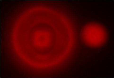
Figure 2, Lighting Comparison of Standard LED and Point Source Emitter. Left is standard LED light ouput, and right is point source emitter.

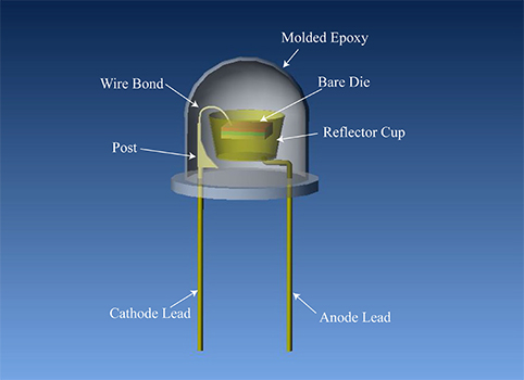
Figure 3, Schematic of Standard LED.

Aperture size, a key parameter of PSEs, can affect power output. A smaller aperture will typically result in a lower power output, however, it will also increase the resolution capability. Point source emitters are offered in a variety of wavelengths and aperture sizes to satisfy individual application requirements. Currently, PSEs are available in wavelengths from red light (650nm) to infrared (IR) light (880nm). More details are presented in Table 1.

Emitting Light ColorWavelengthAperture Window Size
Red650nm25μm
Red650nm80μm
Red650nm150μm
Infrared (IR)850nm50μm
Infrared (IR)850nm150μm
Infrared (IR)880nm (Under Development)50μm
Infrared (IR)880nm (Under Development)150μm


Spectrum Bandwidth For Point Source Emitters

Standard LED emitting light is neither monochromatic like a laser nor broadband like a tungsten lamp, but rather lies in between these two. Hence, output light bandwidth is another significant consideration for different applications. In general, the spectrum bandwidth of LEDs is in 30nm to 100nm range, where PSEs offer a much narrower 20nm—50nm bandwidth. However, some special applications need an even narrower bandwidth. For example, the image system in some microscopy applications require narrow band emissions from the emitter as well as less stray light in the background of the image of the test sample.

Figure 4 shows the spectrum of 880nm standard LED and 880nm PSE. Blue line in this figure represents 880nm standard LED spectrum with 60nm bandwidth; red line stands for spectrum of 880nm PSE. The typical bandwidth of 880nm PSE is 40nm, 20nm less than standard LEDs. This demonstrates that PSEs emit a much tighter monochromatic beam compared to LEDs.

Figure 5 shows the spectrum of 850nm standard and narrow bandwidth PSEs. Green line in this figure is 850nm standard PSE spectrum with 40nm bandwidth; orange line symbolizes spectrum of 850nm PSE with narrow bandwidth. The typical bandwidth of 850nm narrow bandwidth PSEs can reach 25nm; even lower depending on the customer’s requirement.


Spectrum Bandwidth For Point Source Emitters

Characteristically, the luminous intensity of LEDs gradually decreases over the life of the LED. The rate at which the luminous intensity falls varies according to the material used and the forward current at which the LED is driven. The larger the current, the greater the diminution of luminosity. Thus, when setting the forward current of the LED lamp, do not determine the setting solely from the temperature characteristics, as in the above example, but consider also longevity characteristics. An effective way of improving the longevity characteristics is to set the forward current of the LED lamp relatively low.

Viewing Angle For Point Source Emitters

LED viewing angle is primarily a function of chip type, package and optics. Standard LEDs have a viewing angle of 15°-120°. Point source emitters can be offered with narrow viewing angles as narrow as 40 using special optics. There are several technologies that may be utilized to optimize viewing angle including using an external optical glass lens or internal ball lens. These lenses can not only

reduce light loss and optimize the light trace, but also can enhance product reliability. Standard LEDs are typically encased in an epoxy or plastic materials. Some of these encapsulants can chemically react with the die causing premature light output degradation. Many PSEs are packaged in hermetically sealed housings with either air or nitrogen inside. This can significantly improve the life time and output degradation of the PSE. Figure 6 shows an example of an external glass optical lens being applied.

A variety of high reliability package options, including hermetically sealed TO-18 and TO-46 metal cans, coaxial metal can and ceramic surface mount packages can be obtained. All these packages can have varying package heights and lens options, providing the designer with optimum flexibility in sophisticated design efforts. Lens options includes flat glass window, dome lens, etc. Figure 7 shows some standard PSE package styles. Custom package solutions are also available.


Characteristically, the luminous intensity of LEDs gradually decreases over the life of the LED. The rate at which the luminous intensity falls varies according to the material used and the forward current at which the LED is driven. The larger the current, the greater the diminution of luminosity. Thus, when setting the forward current of the LED lamp, do not determine the setting solely from the temperature characteristics, as in the above example, but consider also longevity characteristics. An effective way of improving the longevity characteristics is to set the forward current of the LED lamp relatively low.

Advantages

Applications

LED Lamp